QO-100 LNB Ref Clock Mod
QO-100 LNB with Reference Clock
During the first QSOs on QO-100 I used an unmodified OPTICUM LTP 04H LNB and I had to change the VFO knob every 10s during a QSO.
So it was a really annoying situation, but I already read that on some websites in the internet. We have the factor of ~390 (depending on the
used LNB) between local oscillator and final IF in the LNB.
Let´s modify the LNB from OPTICUM LTP 04H (also available @AMSAT, but nearly 3 times more expensive as an unmodified standard LNB).
Opening the LNB
DH1RK


Navigate
Navigate


I never opened a LNB before, but was relaxed to destroy all the stuff around, I read during my QO-100 investigation.
Remove of Housing, front cover and 10GHz feed.
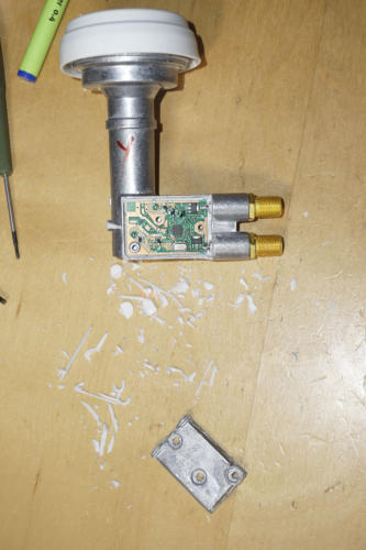
Remove of sealing compound and opening the LNB
with Torx T8 screwdriver.
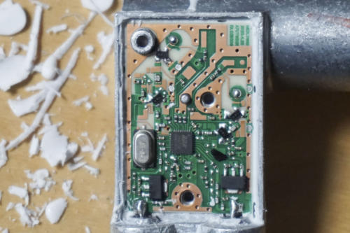
Internal view:
- Quartz to be removed (left side)
Integrated Satellite LNB Tuner (chip) is
RDA3567EM
If someone can provide me a specification from
that chip, drop an E-Mail please.
Thank you in advance.
Modify the LNB (NB only)
Due to limited shipping before christmas I have to wait for the SMD material longer than expected.
I performed the modification for NB only, which means, that “WB LNB” port used as “Reference Clock” input port only, and WB receiving not of
interest at the moment. Check DJ0ABR website (see link list) for correct installation.
•
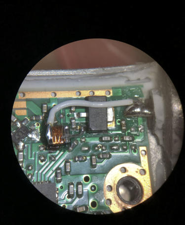
Add series condensator of 100nF on outer port and add connection to ReferenceClock input pin.
•
Remove original inductor nearby the inner port
•
Add series inductor of 4,7uH (or bigger) on inner port to transistor leg
See details on the figures below:
Add sealing compound / glue as weather protection
As a sealing compound I used a special “multi-purpose adhesives” glue from suxun B-7000.
Usually this glue is used for fixing displays in cellphones and has a very thin opening for installation.
Furthermore it is waterproof, flexible and paintable and needs around 24 hours for full curing time.
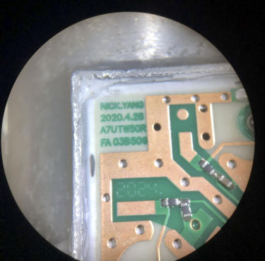
Left:
Version of Opticum LTP 04H LNB device
2020.4.28, A7UTW50R, FA 038509, Nick.Yang
Lower left:
WB LNB input.
Connection from C to PLL input.
Attention: No connection to lower voltage regulator pin (GND).
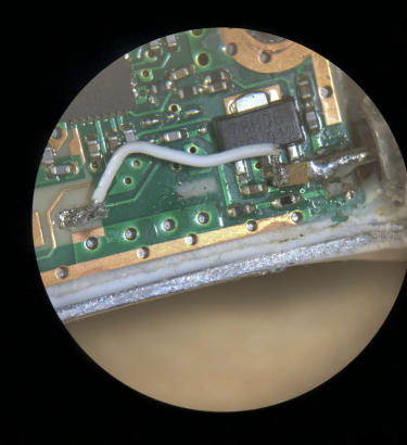
Lower right:
Below the inner port pin, location of removed inductor. New
placement of new inductor with some Instant Adhesive Loctide 401
glue.
Connection from right part of inductor to lower leg of voltage
regulator (Vin) pin.
!! Placement must be flat to avoid short circuits due to top cover. !!
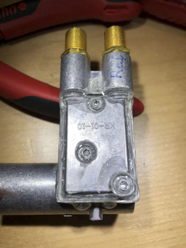
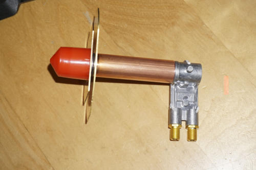
Final installation and connection with the POTY
antenna.


- FK310 AntennaTuner
- Setup 2008
- Inverted L - Simulation
- Inverted L - Installation
- Inverted L - Matching
- SteppIR - Simulation / 20m band
- SteppIR - Simulation / 17m band
- SteppIR - Simulation / 15m band
- SteppIR - Simulation / 12m band
- SteppIR - Simulation / 10m band
- SteppIR - Simulation / 6m band
- SteppIR - Simulation Overview
- SteppIR - Installation
- HighBands -Yagis
- HighBands -Groundplanes
- Setup 2005