LowBand Design
LowBand Antenna Design
Getting The Most Out Of LowFER Transmitting Antennas (K0LR)
Designing an efficient antenna for the 1750-meter band presents a real challenge because of the FCC's 15-meter length restriction. 15 meters
doesn't sound so short until you think of it in terms of wavelength. If I scaled my LowFER antenna for operation on the 20-meter amateur band,
it would be less than 6 inches high, and would look like a wire representation of a Bonsai tree.
The best LowFER antenna systems in operation today probably have efficiencies below 1 per cent. Most of us cannot even expect to approach
that kind of performance; we just do the best we can. This paper briefly discusses the factors involved in LowFER transmitting antenna
efficiency and offers some suggestions on how to get the most out of the resources available to the average experimenter.
Antenna System Components
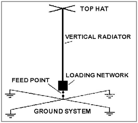
As shown in Figure 1, the essential components of a LowFER antenna system are the ground system, a loading network, a vertical radiating
section and a top hat.
The simplest form of loading network is a coil in series with the antenna. Its purpose is to tune out the capacitive reactance of the antenna and
bring the feed point impedance down to a reasonable level. Although the radiating section can be sloping or bent into any shape, the height
above ground is much more important than the total length. A top hat is optional but highly desirable and can take many different forms. The
objective is to get as much conducting area as you can as high as possible, within practical constraints and FCC limits.
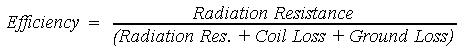
Antenna System Efficiency
The radiation efficiency of the antenna system is given by:
Figure 1.
Anatomy of a LowFER Antenna System
Antenna System Equivalent Circuit
An electrically short antenna looks like a small, lossy capacitor. The radiation "resistance" is a fictitious resistance that accounts for the energy
that is "lost" by radiation (which is actually what we want the antenna to do). The other resistances in the equivalent circuit shown in Figure 2
simply turn RF energy into heat. Radiation resistance is good; all other resistances in the system are bad.
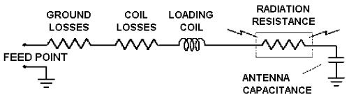
Wire losses aren't shown separately in Figure 2. Although the radio- frequency (RF) resistance of the wire or tubing which makes up the antenna
may be considerably larger than the radiation resistance, it is usually negligible in comparison to ground and coil losses and therefore doesn't
have much effect on overall efficiency. Typically the wire losses represent less than 2 or 3 per cent of the total.
Reducing Coil Loses
Loading coil loss can be reduced indirectly by increasing the antenna capacitance so that less inductance is required, or directly by improving
the quality factor or Q of the coil. Antenna capacitance is approximately proportional to length, so one approach is to make the antenna longer
(but not longer than 15 meters). Increasing the size of the wire or tubing used for the antenna also increases the capacitance, but not very
rapidly. A 15-meter #14 vertical wire above a perfect ground has a capacitance of about 100 pF. Increasing the size of the conductor to 1.5
inches raises the capacity to 150 pF. The best way to increase the capacitance is by adding a top hat. In the examples given later you will see a
reduction of about 3 to 1 in the inductance needed to tune an antenna with a large top hat as compared to a straight vertical wire. It isn't
necessary for the top hat to be a continuous conducting body; a group of radials or a grid of widely spaced wires is almost as effective as a
solid sheet. Computer modeling results show that a "skirt" of #8 aluminum ground wire connecting the outer ends of the four radials shown in
Figure 1 would be more effective than adding four more 1-inch radials. One way to design a top hat is to imagine it supporting a huge sheet of
pizza dough. You want to minimize the sag in the pizza dough with an affordable, erectable structure that can survive ice and wind storms.
Loading coil Q is optimum for a single-layer coil with the wire spacing approximately equal to the wire diameter and with the coil diameter
about twice the coil length. A low-loss form is also important. Materials like Nylon and PVC are poor; polystyrene and Teflon are much better. A
polyethylene 5-gallon pail makes a fairly good coil form. I've also used circles cut from 2-inch thick styrofoam and glued together to get the
required form length.
Adequate wire size is important in the loading coil. I wouldn't recommend anything much smaller than #20. Some dedicated LowFER
enthusiasts use Litz wire in a basket-weave configuration to minimize eddy-current losses and distributed capacitance but it's pricey and hard
to find. Even good old enameled copper "magnet" wire has become hard to find and fairly expensive. I use #14 insulated building wire,
available at discount building-supply stores for as little as $12.00 for a 500-foot spool. Unfortunately the insulation is fairly lossy at 180 kHz. My
LowFER beacon antenna uses a 65- turn basket-wound 2.5 millihenry loading coil, 18 inches diameter by 9 inches long. It has a Q of about 400,
about half of what it could be with low-loss insulation such as Teflon or polyethylene.
Brian Beezly, K6STI has developed a program for the IBM PC that provides accurate inductance and Q calculations for single-layer solenoid
coils, taking into account frequency, wire material and core material. A demonstration copy of COIL.EXE is available on most ham computer
bulletin boards; to get the program to work properly you send Brian a $10.00 registration fee and he provides an activation code.
The radiation resistance of a short antenna is proportional to the square of the antenna height, and loading coil loss decreases with increasing
height (for constant Q). If ground losses could be eliminated, the efficiency would be proportional to the inverse cube of the antenna height.
To maximize the antenna efficiency, we need to make the radiation resistance as high as possible and minimize the ground and coil losses.
Maximizing the efficiency requires a system approach. Working on the ground system and loading network may offer more benefits than
concentrating on the part of the system that we usually think of as the "antenna".
Increase Radiation Resistance
There are basically three ways to increase the radiation resistance of a LowFER antenna:
1) Make the antenna higher.
2) Use a top hat to improve the current distribution in the antenna.
3) Move the loading coil up from the bottom of the radiating section.
The three techniques for raising the radiation resistance are listed in order of effectiveness, with antenna height a hands-down winner.
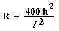
Radiation resistance of a short vertical antenna is approximately:
where the antenna height h and wavelength l are expressed in the same units (feet, meters, etc).
When a horizontal top hat is added to a vertical antenna, the top hat itself doesn't radiate, but it increases the effective height of the vertical
portion. Without a top hat, the current in the antenna decreases toward zero at the top end, and the upper part of the antenna contributes
very little to the total radiation.
For a straight vertical antenna, optimum efficiency is obtained with the loading coil slightly above the center of the radiator. When a large top
hat is used, the loading coil should be closer to the top of the vertical section. Although the placement of the loading coil doesn't have a very
large influence on the efficiency of an antenna mounted "in the clear", it can be fairly significant in the typical LowFER installation. The portion
of the antenna below the coil is at a relatively low impedance and is "cold" enough so that nearby objects have little effect on tuning or losses.
This can be quite important if the lower part of the antenna is close to buildings or vegetation or surrounded by a big wet snowdrift.
Reducing Ground Losses
If you want a really good LowFER transmitting antenna, the first thing to do is to buy about a square mile of salt marsh and put your antenna in
the middle of it, with at least 120 radials a half mile or so in length. It's also fairly effective to use 4 elevated quarter- wave radials (which would
be a quarter mile long for 1750 meters).
Getting down to more practical approaches, some LowFERs get very good results by laying out lengths of chicken wire to form a ground screen
50 feet square or larger, with the pieces soldered together. Another approach is to put out a number of radials, each at least as long as the
antenna height, with several of them terminated at their outer ends in a good earth ground. The more radials the better, but after the first
dozen or so it will probably be hard to see much improvement.
For best results, the conductive ground plane should be at or above earth level. Think of the antenna as a capacitor, with the vertical radiator
acting as one plate and the ground plane acting as the other. We don't want a lossy medium like dirt between the capacitor plates.
Unfortunately, it isn't easy to make an elevated ground screen that enhances the aesthetic appeal of your property, so most LowFER ground
radials are installed below the surface.
When other forms of ground system aren't practical, you can simply run connecting wires from the base of the antenna to all available grounds
such as water pipes, metal buildings or wire fences. Results aren't guaranteed but it will get you on the air.
Lowfer Antenna Examples
To illustrate how the efficiency varies with some of the factors discussed above, we'll look at computer modeling results for three LowFER
antenna examples. The first is a 15-meter (49.2 ft) vertical #14 wire; the second is a T configuration with a 35-foot # 14 vertical wire suspended
from the middle of a 28-foot horizontal # 14 wire, and the third is the suspended flat top antenna currently used for LowFER beacon LEK.
Other Important Factors
Terrain, trees and nearby buildings all have a significant effect on LowFER antenna performance. Nearby trees not only have an undesirable
shielding effect; they also turn a short antenna into a very lossy capacitor. LowFER operators notice that their antenna current improves
dramatically when temperatures drop below freezing and the trees become better insulators. A portable receiver for whistlers and other
"natural radio" phenomena using an E-probe antenna can give a very convincing demonstration of the shielding effects of trees and terrain on
low-frequency electric fields. Signal levels are drastically reduced in the woods as compared to open fields, and are stronger on hilltops than in
valleys.
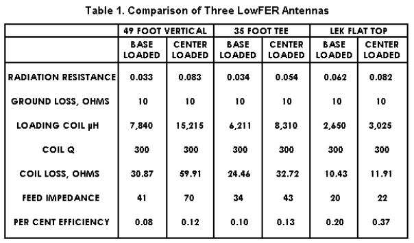
Values of radiation resistance and efficiency presented in Table 1 were computed using K6STI's AO5.0 antenna analysis software. All
calculations assume a coil Q of 300, a ground loss of 10 ohms (optimistic for most LowFER installations, including mine), and a flat ground
plane. The feed impedances given are simply the sums of the radiation resistances and the ground and coil losses, and represent the RF
resistance you should measure between the base of the antenna and ground when the antenna is tuned to resonance.
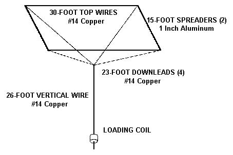
Figure 3.
Flat Top Antenna Used on LowFER Beacon "LEK"
Figure 2.
Equivalent Circuit
The LEK flat top doesn't represent the ultimate in LowFER antennas, but is relatively easy to erect (if a couple of towers or tall trees are
available), and has made it through one year without collapsing. It is suspended by Dacron ropes between two towers and hangs above a 30 by
44 foot metal pole building which serves as the ground plane. All of the #14 copper wire sections are "Flexweave" wire (Purchased from Davis
RF Co, 1-800-484-4002) to avoid problems with kinking. There is a coaxial feedthrough in the roof of the building and the transmitter is located
inside the building, just under the roof. A 4-foot length of PVC pipe supports the loading coil, which has just a little less inductance than needed
to resonate the antenna. A smaller variable inductor between the transmitter and the antenna feedthrough is used for fine tuning. The portion
of the antenna lead-in below the loading coil is "cold" enough so that a buildup of wet snow on the roof has little effect on performance. (Wet
snow on the support ropes is a different story.) Additional down leads and top wires would increase the efficiency slightly but would aggravate
problems with ice and wind loading.
The FCC doesn't specify how to factor top hat dimensions into the 15-meter antenna length limit on the 1750-meter band. A generally accepted
interpretation among experimenters is that the height of the vertical section plus the radius of the top hat cannot exceed 15 meters. The
corresponding dimensions on the LEK antenna are the length of the vertical wire plus the length of the downleads.
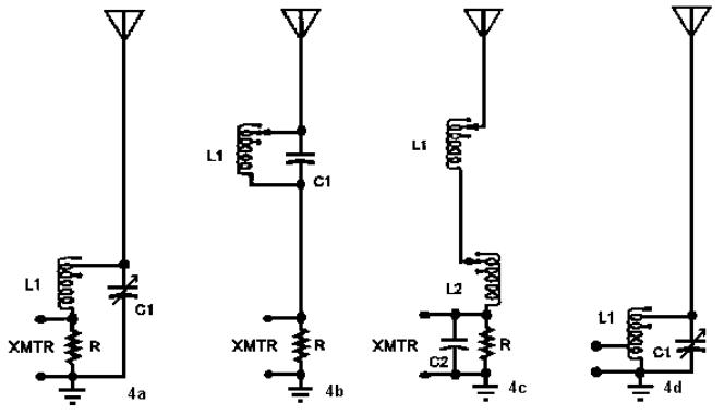
When the loading coil is located some distance above the base of the antenna it becomes more difficult to come up with a simple tuning
scheme. A small variable capacitor connected across the coil can still be used for tuning, as in 4b, but the need for a long tuning shaft can
create some mechanical challenges. I presently use a 2.5 millihenry inductor as the primary loading coil L1, with a much smaller inductor L2
(about 200 microhenries) at the feed point as shown in 4c. The feed point impedance of my antenna is about 30 ohms and my complementary-
pair final is happier driving a slightly higher load impedance, so I use a shunt capacitor C2 of about 0.02 microfarad to improve the impedance
match. I could also use a tap on L2 but the shunt capacitor probably helps reduce harmonic radiation. Resistor R (suggested value 5k ohms, 1
watt) in Figures 4a, 4b and 4c is to provide a direct-current path to ground and keep static charge buildup during snow or dust storms from
zapping the final. Note: Ground the antenna and disconnect the transmitter during thunderstorms!
There are many good designs for LowFER transmitter final stages, not all of which want to see a 50-ohm load. The circuit in 4d uses a loading
coil with two sets of taps, one near the top for coarse tuning of the antenna circuit, and another tap near the ground end for matching the
transmitter output impedance.
I haven't experimented with ferrite or powdered-iron cores for loading coils, but if you can obtain a core made of high-Q material and large
enough to prevent saturation, you can change the coil inductance by varying the core position within the coil. Some other general tips on
loading coils: If you find that you're tapped quite far down on L1, you should remove some turns. Extra turns increase the distributed
capacitance, which decreases Q. Also, don't short any portion of the winding because that really hurts the Q. When you wind the coil, you can
put widely spaced taps on one end and closely spaced taps on the other end to provide a combination of coarse and fine inductance
adjustments. For example, a 100-turn coil could be tapped at 2, 4, 6, 8, 10, 60, 70 ,80 and 90 turns.
Concluding Remarks
Optimizing an antenna for your particular situation will take some head-scratching and a good bit of trial and error. That's part of the fun of
Low Frequency Experimental Radio!
DH1RK


Navigate
Navigate


- FK310 AntennaTuner
- Setup 2008
- Inverted L - Simulation
- Inverted L - Installation
- Inverted L - Matching
- SteppIR - Simulation / 20m band
- SteppIR - Simulation / 17m band
- SteppIR - Simulation / 15m band
- SteppIR - Simulation / 12m band
- SteppIR - Simulation / 10m band
- SteppIR - Simulation / 6m band
- SteppIR - Simulation Overview
- SteppIR - Installation
- HighBands -Yagis
- HighBands -Groundplanes
- Setup 2005